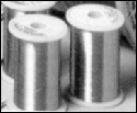
Nickel Chromium Alloy Resistance Heating Wire
80% NICKEL - 20% CHROMIUM

NI/CR-80/20 is the highest development in metallic alloys for use as resistors at elevated temperatures. Processes developed over the years led to steady increase in the ability of this alloy to withstand high temperatures for long duration NI/CR - 80/20 is essential for resistors elements in the higher temperature applications such as electric furnaces, electric ranges, radiant heaters operating at temperatures up to 2100� F. In addition to these qualities and standard uses it has found wide application for resistance in technical applications due to its combination of high electrical resistance and a temperature much less than Nickel Chromium 60.
- Withstands Operating Temperatures To 2100�F
- Corrosion Resistant
- Long Life, Quick Heating
- Formed To Make Helical Coil Heaters
NOMINAL ANALYSIS |
Nickel.............. 78.4% |
Chromium....... 20.0% |
Silicon............. 1.0% |
Iron.................. .5% |
Plus 5 other minor constituents |
CAUTION Products should be installed and used properly to avoid electrical shocks and fire |
Specifications
Melting point: 2550�F (1400� C)
Specific gravity: 8.41
Composition: 80%NI;20%CR
Specific resistance: 650 OHMS per circular mil-foot at 68�F (20�C)
Nominal coefficient of linear expansion: 0.000017(10-1000� C)
Tensile strength at 20�C
Hard Drawn; 200,000 Lbs/in�
Soft Annealed; 100,000 Lbs/in�
Nominal temperature coefficient of resistance: 0.00011 ohms/ohms. �c (20-500�C)
Open Coil Element
AKINSUN open coil elements are precision wound from high quality Nickel-Chromium and other popular heating alloys. Over the years we have produced helical coiled heating elements to meet specific design requirements. Knowing the operating temperature is important. Wire selection is based on operating temperature. Calculation of resistance or the wattage is based on the following ohm law.
Using letters to represent quantity:
R = Resistance (ohms)
W = Watts
E = Volts (Electromotive Force)
I = Current (Amperes)
E = I x R, or I = E/R, R = E/I
The ratio between watts and any two of the above factors is as follows:
W = (ExE)/R = E�/R, W = IxE.
The ratio of a coil is the relationship of its outside diameter to the diameter of the wire. Recommended coil ratio is between 5�:1 and 12:1. Very high and a very low ratio tends to make a coil difficult to manufacture.
Stretch ratio
Stretch ratio of a coil is its stretched length divided by its close wound length. Stretching a coil provides a space between each turn of wire to keep the coils from short circuiting each other and burning out. In order to obtain even heat distribution the spacing between should be uniform. For good heat distribution stretch ratio should be 2:1 to 4:1.
Accessories to Heating Elements
FIBERGLASS SLEEVING | |||||
| 200� C (392� F) For extra insulation and protection where abrasion and heat is a problem. | |||||
|
| SIZE | SLEEVING I.D. | PART NO. | ||
NO.3 | .234 | CP1628-3 | |||
NO.4 | .208 | CP1628-4 | |||
NO.6 | .166 | CP1628-6 | |||
NO.8 | .133 | CP1628-8 | |||
NO.10 | .106 | CP1628-10 | |||
NO.14 | .066 | CP1628-14 | |||
| CERAMIC BEADS | |||||
|
| SIZE | WIRE SIZE B & S | BEAD I.D. | BEADS PER/FT. | |
NO. 2 | NO. 18 | .068 | 84 | ||
NO. 3 | NO. 14 | .092 | 72 | ||
NO. 4 | NO. 12 | .152 | 54 | ||
NO.5 | NO. 10 | .124 | 45 | ||
NO. 6 | NO. 8 | .180 | 37 | ||
| TERMINAL LUG FOR HOOKUP | |||||
|
| Part Number | WIRE GAUGE | SCREW SIZE | ||
CP1653 -6 | 18-22 | 10 | |||
CP1653 -5 | 18-22 | 8 | |||
CP1653 -4 | 14-16 | 10 | |||
CP1653 -3 | 14-16 | 8 | |||
CP1653 -2 | 10-12 | 10 | |||
CP1653 -1 | 10-12 | 8 | |||
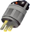
| PLUGS (HUBBELL) | |||||
|
| TYPE | AMP. 120V | Capacity 240V | Part Number MALE | Part Number FEMALE |
Two prong twist lock | 15A | -- | 4520 | 2313 | |
Three Prong Twist Lock | 15A | 10A | 7572G | 7555 | |
Two Prong Straight | 15 A | --- | 5442 | ---- | |
Three Prong Straight | 15A | --- | 5264 | ---- | |
Available in straight and twist lock Prongs, both male and female.
| |||||
| CERAMIC TERMINAL COVERS | |||||
|
| Part Number | Screw Size | |||
CT10-32 | 10-32 | ||||
CT8-32
| 8-32 | ||||
| HIGH TEMPERATURE LEAD WIRE | |||||||
 | Hightemperature Teflon and fiberglass insulated lead wire available in 250°C(482°F), 600 Volts, and 450°C(842°F), 600 Volts. U.L. and C.S.Aapproved. Also available high temperature, Teflon and neoprene leadwire. | Approximatecurrent carrying capacities for insulated wire based on Ambient Temp. of86° F | |||||
| Copper | Ni-CladCopper | Nickel | |||||
| TEFLON-GLASSFIBERGLASS INSULATED HOOK-UP LEAD WIRE ( Ni-Clad Copper conductor) | MICA-GLASSINSULATED HIGH TEMPERATURE HOOK-UP LEAD WIRE ( Ni-Clad Copper conductor) | ||||||
| TYPESTANDARD | NOM.OD., IN. .008/-.006 | TYPESTANDARD | NOM.OD.,IN. +.008/-.006 | ||||
| 7X 30 | 7X 30 | ||||||
| 7X .0121 | 10X 30 | ||||||
| 19X .0092 | 16X 30 | ||||||
| 26X 30 | 26X 30 | ||||||
| 41X 30 | 41X 30 | ||||||
| 65X 30 | 65X 30 | ||||||
| 105X 30 | 105X 30 | ||||||
BUS BAR | |||
 | Good up to 1100 � F, .032 thick X 1/2 IN. wide ORDER CODE: AP1450 | ||
STAINLESS STEEL CONDUIT | |||
| PART NO. | O.D. | I.D. |
CP1621-08 | .234 | .156 | |
CP1621-10 | .312 | .218 | |
CP1621-12 | .344 | .250 | |
CP1621-16S | .438 | .344 | |
| Used for protection of lead wire. | CP1621-16 | .500 | .375 |
SILICONE FIBERGLASS TAPE |
|
| 7 Mils thick, Pressure sensitive 1/2 in. wide, adhesive tape good up to 350� F (175� C) 108 ft. long ORDER CODE: CP 1667 |
Ceramic Heaters
Ceramic heaters of various shapes and forms are made of the highest quality refractory ceramic with heating coils of nickel chromium resistance wire.
Coils are imbedded in grooves and sometimes cemented in place when the application calls for it.
Application
- Resistor Element
- Radiant Heater
- Air Heater
- Dehumidifier
- Cabinet Heating
- Surface Heating
- Packaging
- Oven Heating
Features
- Available 120, 208, 240 and 480V
- Leads termination available
- Mounting ease
- Single bolt type mounting
- Screw in type mounting
- Threaded rod through type mounting
CERAMIC DISC HEATER | PART NO. | WATTS | VOLTS | ||
| CS1032-1 | 250 | 120V | ||
CS1032-2 | 250 | 240V | |||
3 1/8" O.D. x 11/16 Thick 6-32 Screw terminals .205 Diameter center hole for mounting
| |||||
| CERAMIC CONE HEATER | |||||
| PART NO. | WATTS | VOLTS | ||
CS1003-01 | 500 | 120V | |||
CS1003-02 | 660 | 120V | |||
CS1003-03 | 660 | 208V | |||
CS1003-04 | 660 | 240V | |||
CS1003-05 | 1000 | 120V | |||
CS1003-06 | 1000 | 240V | |||
4 1/8" Long tapered Edison screw base mounting | |||||
CERAMIC "EHT" HEATER | PART NO. | WATTS | VOLTS | ||
| EHT-0001 | 3000 | 240 | ||
EHT-0003 | 2002 | 240 | |||
EHT-0005 | 3500 | 240 | |||
EHT-0007 | 2500 | 240 | |||
EHT-0008 | 2000 | 115 | |||
EHT-0011 | 2500 | 208 | |||
EHT-0013 | 1500 | 240 | |||
10-32 Screw terminals. Center hole 3/8" diameter is used for mounting | |||||
Note: Watts and Volts other than listed are also available. Please contact the factory.
Crydom Relay
Solid-state Relays (SSRs) are electronic switching devices that accept a time proportioned or on /off signal from a controller. Rapid cycling can wear out electromechanical relay, whereas SSRs operate at much smaller cycle times. Therefore, SSRs can be employed where extremely tight process control is required and when durability is a necessity. The life of a heating element is increased considerably when the on/off cycle that is used to time-proportion the heater is kept at 1 or 2 seconds, or less, thus reducing the thermal expansion and contraction of element. The fast cycling SSRs ensure longer heater life at lower cost. In addition, temperature control is optimized with the faster cycling SSRs compared to electromechanical relays.
Since SSRs have no moving parts, mechanical failure is eliminated. They are resistant to shock and vibration and are durable if operated within the tolerable ambient temperatures. Heat sinks will efficiently dissipate the heat thereby increasing each unit�s life.
Relays are compact, typically measuring 58.4 (H) x 45.7 (W) x 22.9 (D) mm.
Crydom Relays
120/240 VOLT
AC OUTPUT
- Zero Voltage and Random turn-on Switching
- Panel Mount
Featuring state-of-the-art Surface Mount Technology, these SPST-NO relays delivers proven reliability in the most demanding applications. Output consists of an SCR AC switch and is available in zero-cross, random turn-on (phase controllable) and normally closed (Form B) versions with either AC or DC input (coil) control.
DC CONTROL - SCR OUTPUT | ||||||
Crydom Model Number | Line Voltage Range (Vac) | Load Current Range (Arms) | Control Voltage Range (Vdc) | Control Current @ 5Vdc (mA) | Must Release Voltage (Vdc) | Surge Current 1-Cycle (Apk) |
D2410 | 24-280 | .04-10 | 3-32 | 3.4 | 1.0 | 120 |
D2425 | 24-280 | .04-25 | 3-32 | 3.4 | 1.0 | 250 |
D2450 | 24-280 | .04-50 | 3-32 | 3.4 | 1.0 | 625 |
AC CONTROL - SCR OUTPUT | ||||||
Crydom Model Number | Line Voltage Range (Vac) | Load Current Range (Arms) | Control Voltage Range (Vac) | Control Current @120Vac (mA) | Must Release Voltage (Vac) | Surge Current 1-Cycle (Apk) |
A2410 | 24-280 | .04-10 | 90-280 | 2.0 | 10.0 | 120 |
A2425 | 24-280 | .04-25 | 90-280 | 2.0 | 10.0 | 250 |
* A2450 | 24-280 | .04-50 | 90-280 | 2.0 | 10.0 | 625 |
* Stocked as A2440 with same specification. | ||||||
GENERAL SPECIFICATIONS
Operating Temperature Range: | -40� to 80� C |
Isolation Voltage: | 4000 Vrms |
Minimum Off-State dv/dt: | 500V/m sec |


